8/25:
"Qualities you see in others, reveal something about you."
You may not realize it, but the characteristics you like or dislike in others delivers a special message.
If you respond to a person that you see as outgoing, positive and energetic, these are most likely qualities you possessed, but have not fully embraced or developed. Likewise, if you react to the overbearing nature of another, then do a self check,you may have tendency to be overbearing yourself.
Either way, turn into what you do and don't admire in others. Take notes of your emotion response. With this new found awareness you can't help but discover something you didn't know about yourself.
Today's affirmation:The qualities I respond to in others reflect who I am.
8/26:
I will waste not even a precious second today in anger or hate or jealousy or selfishness. I know that the seeds I sow I will harvest, because every action, good or bad, is always followed by an equal reaction. I will plant only good seeds this day.
-Og Mandino 1923-1996, Author and Speaker
9/17:
"Happiness is not the destination."
Many people slog for a lifetime looking for happiness. They feel guilty doing things they enjoy. So they take care of their jobs, their families and their children thinking that the time for happiness will come later. In the end, they discover that it doesn't.
Believe that you deserve happiness right now!
You know those early hours in the morning when the house is quiet and the mist is floating outside the window? That is happiness. Remember how it felt to hold your baby for the first time? That is happiness. Remember how you felt when you achieved what seemed like an impossible goal? That is happiness.
Do not defer your happiness to a later date. Find joy in what you do every day.
Today's affirmation: I deserve to be happy right now.
10/5
"Admit your mistake! It's your most empowering choice."
We all make mistakes. It's a fact of life. What matters is what you do afterward.
You have a choice. You can let your mistake torment you, embarrass you, and hold you back. Or, you can admit you made a mistake, learn from it, and move on.
Mistakes are lessons in disguise. You can learn something from each and every one. Next time, you make a mistake, act quickly and decisively. Take responsibility and look for the lesson. Use the lesson to reach greater success and good fortune in your life.
Learn from your mistakes. Only then can they empower you to greater heights.
Today's affirmation: I admit my mistakes and learn from them.
Monday, August 23, 2010
HA: NSB NSR ISSU
Modern high-performance routers architecturally separate the forwarding plane and the control plane into separate physical components, each with its own memory and processors. The control plane runs the routing protocols, maintains the necessary databases for route processing, and derives a forwarding table (FIB). The FIB is given to the forwarding plane, which is responsible for packet forwarding.
In fact the control plane could stop functioning altogether and because the forwarding plane is a separate entity with its own processors it can continue forwarding packets based on its copy of the FIB. This is Non-Stop Forwarding (NSF): The ability of the forwarding plane to continue running “headless” if the control plane stops.
Of course this is dangerous; if the network topology changes while the control plane is down there is no way to process new route information and the forwarding plane’s FIB can become invalid, resulting in incorrectly forwarded packets. So why would you even want NSF?
The answer is redundant control planes (Cisco calls their control planes Route Processors; Juniper calls them Routing Engines). NSF allows you to switch from a primary to a backup control plane without disrupting forwarding. The FIB could still become invalid during the period between when the primary control plane goes down and the backup control plane takes over, but the risk in this period is usually an acceptable compromise.
So if the backup control plane maintains a copy of the active configuration and current state on system components such as interfaces, it can become active much faster than if it had to learn all this information first. Cisco calls this Stateful Switchover (SSO) and Juniper calls it Graceful Routing Engine Switchover (GRES).
The problem with control plane switchovers as so far described, even if it uses stateful procedures to decrease the switchover time, is that routing protocol adjacencies are broken by the switchover. When a primary control plane goes down any neighboring router that had a peering session with it sees the peering session fail. When the backup control plane becomes active it re-establishes the adjacency, but in the interim the neighbor has advertised to its own neighbors that router X is no longer a valid next hop to any destinations beyond it, and the neighbors should find another path. And of course when the backup control plane comes on-line and reestablishes adjacencies its neighbors advertise the information that router X is again available as a next hop and everyone should again recalculate best paths. All of this is can be highly disruptive to the network.
The objective of NSR is to prevent, or at least minimize, the effect of broken peering sessions.
A first attempt at controlling broken adjacencies during control plane switchovers is Graceful Restart (GR) protocol extensions. Each routing protocol has its own specific GR extensions, but they all work pretty much the same. When a router’s control plane goes down its neighbors, rather than immediately reporting to their own neighbors that the router has become unavailable, wait a certain amount of time (the grace period). If the router’s control plane comes back up and reestablishes its peering sessions before the grace period expires, as would be the case during a control plane switchover, the temporarily broken peering sessions do not effect the network beyond the neighbors.
There are, however, a couple of problems with GR:
.Neighbors are required to support the GR protocol extensions. yet small CE routers are less likely to support GR.
.If there is a complete control plane or router failure rather than just a switchover, the GR grace period can slow network reconvergence.
A newer generation of NSR uses internal processes to keep the backup control plane aware of routing protocol state and adjacency maintenance activities, so that after a switchover the backup control plane can take charge of the existing peering sessions rather than having to establish new ones. The switchover is then transparent to the neighbors, and because the NSR process is internal (and vendor specific) there is no need for the neighbors to support any kind of protocol extension.
Here’s where the confusion comes in: Different vendors use these terms differently. Juniper, for example, calls its graceful restart implementation Graceful Restart, whereas Cisco calls its graceful restart implementation Non-Stop Forwarding Awareness (even though GR applies to routing, not forwarding). Juniper users often confuse GRES and GR: Although the “G” in both acronyms stands for “Graceful,” GRES and GR are two different things. And both Cisco and Juniper have internal NSR capabilities, but the circumstances in which each can be used are quite different.
So enjoy the circus, but be aware that different vendors sometimes use different names for essentially the same act. When a vendor talks about NSF, GR, and NSR, be sure you know that vendor’s.
RPR
RPR enables a quicker switchover between an active and standby RSP if the active RSP experiences a fatal error. When you configure RPR, the standby RSP loads a Cisco IOS image on bootup and initializes itself in standby mode. In the event of a fatal error on the active RSP, the system switches to the standby RSP, which reinitializes itself as the active RSP, reloads all of the line cards, and restarts the system.
RPR+
The RPR+ feature is an enhancement of the RPR feature. RPR+ keeps the VIPs from being reset and reloaded when a switchover occurs between the active and standby RSPs. Because VIPs are not reset and microcode is not reloaded on the VIPs, and the time needed to parse the configuration is eliminated, switchover time is reduced to 30 seconds.
SSO
SSO establishes one of the supervisor engines as active while the other supervisor engine is designated as standby, and then SSO synchronizes information between them. A switchover from the active to the redundant supervisor engine occurs when the active supervisor engine fails, or is removed from the router, or is manually shut down for maintenance. This type of switchover ensures that Layer 2 traffic is not interrupted.
SSO switchover preserves FIB and adjacency entries and can forward Layer 3 traffic after a switchover. Configuration information and data structures are synchronized from the active to the redundant supervisor engine at startup and whenever changes to the active supervisor engine configuration occur.
ISSU: In-Service Software Upgrade (ISSU) CISCO
Requires Dual RE
1. Primary and Standby Supervisors Running Current Image
2. Load New Image on Standby Supervisor
3. Make Standby Supervisor “Active” (<150ms)—Switch Now Running New Image
4. Rapid Rollback Option (<150ms) if Necessary
5. Load New Image on Primary Supervisor and Commit Change
Friday, August 13, 2010
IP Header
Defined at RFC 791
A summary of the contents of the internet header follows:
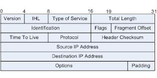
Version: 4 bits
The Version field indicates the format of the internet header.
4 - ipv4
6 - ipv6
IHL: 4 bits
Internet Header Length is the length of the internet header in 32
bit words, and thus points to the beginning of the data.
5 - minimum value without option
Type of Service: 8 bits
Bits 0-2: Precedence.
Bit 3: 0 = Normal Delay, 1 = Low Delay.
Bits 4: 0 = Normal Throughput, 1 = High Throughput.
Bits 5: 0 = Normal Relibility, 1 = High Relibility.
Bit 6-7: Reserved for Future Use.
0 1 2 3 4 5 6 7
+-----+-----+-----+-----+-----+-----+-----+-----+
| | | | | | |
| PRECEDENCE | D | T | R | 0 | 0 |
| | | | | | |
+-----+-----+-----+-----+-----+-----+-----+-----+
Precedence
111 - Network Control
110 - Internetwork Control
101 - CRITIC/ECP
100 - Flash Override
011 - Flash
010 - Immediate
001 - Priority
000 - Routine
Total Length: 16 bits
Total Length is the length of the datagram, measured in octets, including internet header and data.
Identification: 16 bits
An identifying value assigned by the sender to aid in assembling the
fragments of a datagram.
Flags: 3 bits
Various Control Flags.
Bit 0: reserved, must be zero
Bit 1: (DF) 0 = May Fragment, 1 = Don't Fragment.
Bit 2: (MF) 0 = Last Fragment, 1 = More Fragments.
0 1 2
+---+---+---+
| | D | M |
| 0 | F | F |
+---+---+---+
Fragment Offset: 13 bits
This field indicates where in the datagram this fragment belongs.
The fragment offset is measured in units of 8 octets (64 bits). The
first fragment has offset zero.
Time to Live: 8 bits
This field indicates the maximum time the datagram is allowed to
remain in the internet system.
Protocol: 8 bits
This field indicates the next level protocol used in the data
portion of the internet datagram. The values for various protocols
are specified in "Assigned Numbers" RFC 1700
1 - ICMP
2 - IGMP
6 - tcp
17 - udp
47 - GRE
88 - IGRP
Header Checksum: 16 bits
A checksum on the header only. Since some header fields change
(e.g., time to live), this is recomputed and verified at each point
that the internet header is processed.
Source Address: 32 bits
The source address.
Destination Address: 32 bits
The destination address.
Options: variable
The options may appear or not in datagrams.
IGMP
There are three versions of IGMP, IGMP v1 is defined by RFC 1112, IGMP v2 is defined by RFC 2236 and IGMP v3 is defined by RFC 3376.
IGMPv3 improves over IGMPv2 mainly by adding the ability to listen to multicast originating from a set of IP addresses only.
IGMP V1
IGMP V2
IGMP V3
IGMPv3 improves over IGMPv2 mainly by adding the ability to listen to multicast originating from a set of IP addresses only.
IGMP V1
IGMP V2
IGMP V3
Thursday, August 12, 2010
Ip routing Q&A
1.
Q: what are the administrative distances for routing protocols ?
A:
Directly connected route ------------ 0
Static route out an interface -------- 0
Static route to next-hop address ----- 1
EIGRP summary route ------------------ 5
External BGP ------------------------- 20
Internal EIGRP ----------------------- 90
IGRP --------------------------------- 100
OSPF --------------------------------- 110
IS-IS -------------------------------- 115
RIP ---------------------------------- 120
EGP ---------------------------------- 140
ODR ---------------------------------- 160
External EIGRP ----------------------- 170
Internal BGP ------------------------- 200
DHCP-learned ------------------------- 254
Unknown ------------------------------ 255
Notes:
An administrative distance of 255 will cause the router to disbelieve the route entirely and not use it.
Since IOS 12.2, the administrative distance of a static route with an exit interface is 1. Prior to the release of 12.2 it was in fact 0.
2.
Q: Can administrative distance be changed ?
A: You can modify the administrative distance of a protocol through the distance command. (CISCO)
3.
Q. What are private IP addresses?
A. The Internet Assigned Numbers Authority (IANA) has reserved the following three blocks of the IP address space for private internets (RFC1918)
10.0.0.0 - 10.255.255.255 (10/8 prefix)
172.16.0.0 - 172.31.255.255 (172.16/12 prefix)
192.168.0.0 - 192.168.255.255 (192.168/16 prefix)
4.
Q. well known reserved ipv4 multicast address ?
A. reserved for IP multicasting and registered with the Internet Assigned Numbers Authority (IANA)
224.0.0.0 Base address (reserved)
224.0.0.1 All systems on the same network segment
224.0.0.2 All routers on the same network segment
224.0.0.5 OSPF AllSPFRouters address. Used to send Hello packets to all OSPF routers on a network segment
224.0.0.6 The OSPF AllDRouters address. Used to send OSPF routing information to OSPF designated routers on a network segment
224.0.0.9 The RIP version 2 group address. Used to send routing information using the RIP protocol to all RIP v2-aware routers on a network segment
224.0.0.10 EIGRP group address. Used to send EIGRP routing information to all EIGRP routers on a network segment
224.0.0.13 PIM Version 2 (Protocol Independent Multicast)
224.0.0.18 VRRP
224.0.0.19 - 21 IS-IS over IP
224.0.0.22 IGMP Version 3 (Internet Group Management Protocol)
224.0.0.102 Hot Standby Router Protocol Version 2
224.0.0.251 Multicast DNS address
224.0.0.252 Link-local Multicast Name Resolution address
224.0.1.1 Network Time Protocol address
224.0.1.39 Cisco Auto-RP-Announce address
224.0.1.40 Cisco Auto-RP-Discovery address
224.0.1.41 H.323 Gatekeeper discovery address
5.
Q. what is unregistered multicast packet ?
A. RFC4541: An unregistered packet is defined as an IPv4 multicast packet with a destination address which does not match any of the groups announced in earlier IGMP Membership Reports.
If a switch receives an unregistered packet, it must forward that packet on all ports to which an IGMP router is attached. A switch may default to forwarding unregistered packets on all ports.
Switches that do not forward unregistered packets to all ports must include a configuration option to force the flooding of unregistered packets on specified ports.
6.
Q: ethernet header format ?
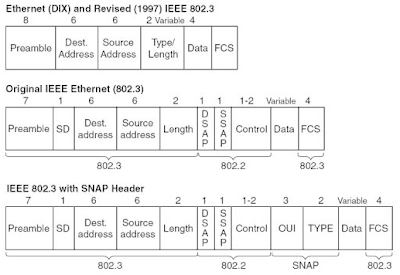
A.
Ethernet type II: Type at the type/Length
IEEE 802.3 Frame:
IEEE 802.3 with SNAP header
802.3 Raw: Length at type/length. Novell's non-standart Same as 802.3, without the IEEE 802.2 LLC header. Novell's IPX is the only protocol that uses the 802.3 raw frame type
7.
Q: how to identify Ethernet type ?
A:
1. if the Type/Length field has higher than (0x05Dc), then it is Ethernet II, the Type/Length is type and date is followed immeditately.
2.If it is length, if DSAP is 0xAA, then it has SANP header.
3. For 802.3 Raw: Novell decided to use the first two bytes in the data portion of the packet, the IPX checksum field, to identify an 802.3 raw frame using the IPX/SPX protocol. All LAN drivers would use the value 0xFFFF in these two bytes to designate the packet as 802.3 raw.
3.
8.
Q. well known ether type:
A: For detail, please check RFC5342
0x0000 - 0x05DC: IEEE 802.3 length
0x0800 : IP
0x0806: ARP
0x86DD: Ipv6
9.
Q. what is L2TP ?
A: The Layer 2 Tunnel Protocol (L2TP) is IETF standard that combines two existing tunneling protocols: Cisco's Layer 2 Forwarding (L2F) and Microsoft's Point-to-Point Tunneling Protocol (PPTP). L2TP is an extension to the Point-to-Point Protocol (PPP), which is an important component for VPNs.
Although L2TP acts like a Data Link Layer protocol in the OSI model, L2TP is in fact a Session Layer protocol,[2] and uses the registered UDP port 1701.
10.
Q. What is L2PT ?
A. Layer 2 protocol tunneling allows Layer 2 protocol data units (PDUs) (CDP, STP, and VTP) to be tunneled through a network.
Juniper EX switch support L2PT from 10.0.
Thursday, August 5, 2010
BGP
The BGP, which is defined at RFC 1771 allows you to create loop-free interdomain routing between autonomous systems (ASs). An AS is a set of routers under a single technical administration. Routers in an AS can use IGP to exchange routing information.
BGP uses TCP with port 179. Two BGP routers form a TCP connection between one another.
When BGP runs between routers that belong to two different ASs, this is called exterior BGP (eBGP). When BGP runs between routers in the same AS, this is called iBGP.
The use of a loopback interface to define neighbors is common with iBGP, but is not common with eBGP.
If you use the IP address of a loopback interface in the neighbor command, you need some extra configuration on the neighbor router.
neighbor ip-address update-source interface
For eBGP, if you use non directed connected interface address as neighbor, ebgp-mulihop is needed. The multihop is only for eBGP and not for iBGP. You still need to make sure the neighor is reachable at both sides. You can configure an IGP or static routing.
There is heavy use of route maps with BGP. In the BGP context, the route map is a method to control and modify routing information. The control and modification of routing information occurs through the definition of conditions for route redistribution from one routing protocol to another. Or the control of routing information can occur at injection in and out of BGP.
There are two instances of the route map defined at below, with the name MYMAP. The first instance has a sequence number of 10, and the second has a sequence number of 20.
route-map MYMAP permit 10 (The first set of conditions goes here.)
route-map MYMAP permit 20 (The second set of conditions goes here.)
When you apply route map MYMAP to incoming or outgoing routes, the first set of conditions are applied via instance 10. If the first set of conditions is not met, you proceed to a higher instance of the route map.
Each route map consists of a list of match and set configuration commands. The match specifies a match criteria, and set specifies a set action if the criteria that the match command enforces are met.
If the match criteria are met and you have a permit, there is a redistribution or control of the routes, as the set action specifies. You break out of the list.
If the match criteria are met and you have a deny, there is no redistribution or control of the route. You break out of the list.
If the match criteria are not met and you have a permit or deny, the next instance of the route map is checked. This next-instance check continues until you either break out or finish all the instances of the route map. If you finish the list without a match, the route is not accepted nor forwarded.
The related commands for match are:
match as-path
match community
match clns
match interface
match ip address
match ip next-hop
match ip route-source
match metric
match route-type
match tag
The related commands for set are:
set as-path
set clns
set automatic-tag
set community
set interface
set default interface
set ip default next-hop
set level
set local-preference
set metric
set metric-type
set next-hop
set origin
set tag
set weight
There are multiple ways to send network information with use of BGP:network Command, Redistribution, Static Routes and Redistribution
network network-number [mask network-mask]
The network command controls the networks that originate from this box. The command uses a mask portion because BGP version 4 (BGP4) can handle subnetting and supernetting. A maximum of 200 entries of the network command are acceptable. The network command works if the router knows the network that you attempt to advertise, whether connected, static, or learned dynamically.
Another way is to redistribute your IGP into BGP. Apply careful filtering to make sure that you send to the Internet-only routes that you want to advertise and not to all the routes that you have.
You can always use static routes to originate a network or a subnet. The only difference is that BGP considers these routes to have an origin that is incomplete, or unknown
Redistribution is always the method for injection of BGP into IGP
Remember that when a BGP speaker receives an update from other BGP speakers in its own AS (iBGP), the BGP speaker that receives the update does not redistribute that information to other BGP speakers in its own AS. The BGP speaker that receives the update redistributes the information to other BGP speakers outside of its AS. Therefore, sustain a full mesh between the iBGP speakers within an AS.
BGP Decision Algorithm
After BGP receives updates about different destinations from different autonomous systems, the protocol must choose paths to reach a specific destination. BGP chooses only a single path to reach a specific destination.
BGP bases the decision on different attributes, such as next hop, administrative weights, local preference, route origin, path length, origin code, metric, and other attributes.
BGP always propagates the best path to the neighbors.
BGP assigns the first valid path as the current best path. BGP then compares the best path with the next path in the list, until BGP reaches the end of the list of valid paths. This list provides the rules that are used to determine the best path:
1. Prefer the path with the highest WEIGHT.
Note: WEIGHT is a Cisco-specific parameter. It is local to the router on which it is configured.
2. Prefer the path with the highest LOCAL_PREF.
Note: A path without LOCAL_PREF is considered to have had the value set with the bgp default local-preference command, or to have a value of 100 by default.
3. Prefer the path that was locally originated via a network or aggregate BGP subcommand or through redistribution from an IGP.
Local paths that are sourced by the network or redistribute commands are preferred over local aggregates that are sourced by the aggregate-address command.
4.Prefer the path with the shortest AS_PATH.
. This step is skipped if you have configured the bgp bestpath as-path ignore command.
.An AS_SET counts as 1, no matter how many ASs are in the set.
.The AS_CONFED_SEQUENCE and AS_CONFED_SET are not included in the AS_PATH length.
5. Prefer the path with the lowest origin type.
Note: IGP is lower than Exterior Gateway Protocol (EGP), and EGP is lower than INCOMPLETE.
6. Prefer the path with the lowest multi-exit discriminator (MED).
Note: Be aware of these items:
.This comparison only occurs if the first (the neighboring) AS is the same in the two paths. Any confederation sub-ASs are ignored.
In other words, MEDs are compared only if the first AS in the AS_SEQUENCE is the same for multiple paths. Any preceding AS_CONFED_SEQUENCE is ignored.
.If bgp always-compare-med is enabled, MEDs are compared for all paths.
You must disable this option over the entire AS. Otherwise, routing loops can occur.
. If bgp bestpath med-confed is enabled, MEDs are compared for all paths that consist only of AS_CONFED_SEQUENCE.
These paths originated within the local confederation.
.THE MED of paths that are received from a neighbor with a MED of 4,294,967,295 is changed before insertion into the BGP table. The MED changes to to 4,294,967,294.
.Paths received with no MED are assigned a MED of 0, unless you have enabled bgp bestpath med missing-as-worst .
If you have enabled bgp bestpath med missing-as-worst, the paths are assigned a MED of 4,294,967,294.
.The bgp deterministic med command can also influence this step.
Refer to How BGP Routers Use the Multi-Exit Discriminator for Best Path Selection
7. Prefer eBGP over iBGP paths.
If bestpath is selected, go to Step 9 (multipath).
Note: Paths that contain AS_CONFED_SEQUENCE and AS_CONFED_SET are local to the confederation. Therefore, these paths are treated as internal paths. There is no distinction between Confederation External and Confederation Internal.
8. Prefer the path with the lowest IGP metric to the BGP next hop.
Continue, even if bestpath is already selected.
9. Determine if multiple paths require installation in the routing table for BGP Multipath.
Continue, if bestpath is not yet selected.
10. When both paths are external, prefer the path that was received first (the oldest one).
Skip this step if any of these items is true:
.You have enabled the bgp best path compare-routerid command.
. The router ID is the same for multiple paths because the routes were received from the same router.
. There is no current best path.
The current best path can be lost when, for example, the neighbor that offers the path goes down.
11. Prefer the route that comes from the BGP router with the lowest router ID.
The router ID is the highest IP address on the router, with preference given to loopback addresses. Also, you can use the bgp router-id command to manually set the router ID.
Note: If a path contains route reflector (RR) attributes, the originator ID is substituted for the router ID in the path selection process.
12. If the originator or router ID is the same for multiple paths, prefer the path with the minimum cluster list length.
This is only present in BGP RR environments. It allows clients to peer with RRs or clients in other clusters. In this scenario, the client must be aware of the RR-specific BGP attribute.
13. Prefer the path that comes from the lowest neighbor address.
This address is the IP address that is used in the BGP neighbor configuration. The address corresponds to the remote peer that is used in the TCP connection with the local router.
BGP attribute
As_path Attribute
Whenever a route update passes through an AS, the AS number is prepended to that update. The AS_path attribute is actually the list of AS numbers that a route has traversed in order to reach a destination. An AS-SET is an ordered mathematical set {} of all the ASs that have been traversed.
In the above example, network 190.10.0.0 is advertised by RTB in AS200, when that route traverses AS300 and RTC will append its own AS number to it. So when 190.10.0.0 reaches RTA it will have two AS numbers attached to it: first 200 then 300. So as far as RTA is concerned the path to reach 190.10.0.0 is (300,200).
Origin Attribute
The origin is a mandatory attribute that defines the origin of the path information. The origin attribute can assume three values:
IGP: Network Layer Reachability Information (NLRI) is interior to the originating AS. This normally happens when we use the bgp network command or when IGP is redistributed into BGP, then the origin of the path info will be IGP. This is indicated with an "i" in the BGP table.
EGP: NLRI is learned via EGP (Exterior Gateway Protocol). This is
indicated with an "e" in the BGP table.
INCOMPLETE: NLRI is unknown or learned via some other means. This usually occurs when we redistribute a static route into BGP and the origin of the route will be incomplete. This is indicated with an "?" in the BGP table.
Nexthop Attribute
The BGP nexthop attribute is the next hop IP address that is going to be used to reach a certain destination. For EBGP, the next hop is always the IP address of the neighbor specified in the neighbor command.
Special care should be taken when dealing with multiaccess and NBMA networks.
BGP Nexthop (Multiaccess Networks)
Assume that RTC and RTD in AS300 are running OSPF. RTC is running BGP with RTA. RTC can reach network 180.20.0.0 via 170.10.20.3. When RTC sends a BGP update to RTA regarding 180.20.0.0 it will use as next hop 170.10.20.3 and not its own IP address (170.10.20.2). This is because the network between RTA, RTC and RTD is a multiaccess network and it makes more sense for RTA to use RTD as a next hop to reach 180.20.0.0 rather than making an extra hop via RTC.
*RTC will advertise 180.20.0.0 to RTA with a NextHop 170.10.20.3.
BGP Nexthop (NBMA)
BGP backdoor
Usually when a route is learned via EBGP, it is installed in the IP routing table because of its distance (20). Sometimes, however, two ASs have an IGP-learned backdoor route and an EBGP-learned route. Their policy might be to use the IGP-learned path as the preferred path and to use the EBGP-learned path when the IGP path is down.
All igps default distances are higher than the default distance of EBGP (which is 20). Usually, the route with the lowest distance is preferred.
If you want igp routes be chosen, you could use one of the following techniques:
.Change the external distance of EBGP. (Not recommended because the distance will affect all updates, which might lead to undesirable behavior when multiple routing protocols interact with one another.)
•Change the distance of the IGP. (Not recommended because the distance will affect all updates, which might lead to undesirable behavior when multiple routing protocols interact with one another.)
•Establish a BGP back door. (Recommended)
To establish a BGP back door, use the network backdoor router configuration command.
router bgp 100
network 160.10.0.0 backdoor
with the network backdoor command, Router A treats the EBGP-learned route as local and installs it in the IP routing table with a distance of 200. The network is also learned igp, so it is successfully installed in the IP routing table and is used to forward traffic. If the Enhanced IGP-learned route goes down, the EBGP-learned route will be installed in the IP routing table and used to forward traffic.
Configuration sample:
links:
bgp case study
bgp tutorial
BGP uses TCP with port 179. Two BGP routers form a TCP connection between one another.
When BGP runs between routers that belong to two different ASs, this is called exterior BGP (eBGP). When BGP runs between routers in the same AS, this is called iBGP.
The use of a loopback interface to define neighbors is common with iBGP, but is not common with eBGP.
If you use the IP address of a loopback interface in the neighbor command, you need some extra configuration on the neighbor router.
neighbor ip-address update-source interface
For eBGP, if you use non directed connected interface address as neighbor, ebgp-mulihop is needed. The multihop is only for eBGP and not for iBGP. You still need to make sure the neighor is reachable at both sides. You can configure an IGP or static routing.
There is heavy use of route maps with BGP. In the BGP context, the route map is a method to control and modify routing information. The control and modification of routing information occurs through the definition of conditions for route redistribution from one routing protocol to another. Or the control of routing information can occur at injection in and out of BGP.
There are two instances of the route map defined at below, with the name MYMAP. The first instance has a sequence number of 10, and the second has a sequence number of 20.
route-map MYMAP permit 10 (The first set of conditions goes here.)
route-map MYMAP permit 20 (The second set of conditions goes here.)
When you apply route map MYMAP to incoming or outgoing routes, the first set of conditions are applied via instance 10. If the first set of conditions is not met, you proceed to a higher instance of the route map.
Each route map consists of a list of match and set configuration commands. The match specifies a match criteria, and set specifies a set action if the criteria that the match command enforces are met.
If the match criteria are met and you have a permit, there is a redistribution or control of the routes, as the set action specifies. You break out of the list.
If the match criteria are met and you have a deny, there is no redistribution or control of the route. You break out of the list.
If the match criteria are not met and you have a permit or deny, the next instance of the route map is checked. This next-instance check continues until you either break out or finish all the instances of the route map. If you finish the list without a match, the route is not accepted nor forwarded.
The related commands for match are:
match as-path
match community
match clns
match interface
match ip address
match ip next-hop
match ip route-source
match metric
match route-type
match tag
The related commands for set are:
set as-path
set clns
set automatic-tag
set community
set interface
set default interface
set ip default next-hop
set level
set local-preference
set metric
set metric-type
set next-hop
set origin
set tag
set weight
There are multiple ways to send network information with use of BGP:network Command, Redistribution, Static Routes and Redistribution
network network-number [mask network-mask]
The network command controls the networks that originate from this box. The command uses a mask portion because BGP version 4 (BGP4) can handle subnetting and supernetting. A maximum of 200 entries of the network command are acceptable. The network command works if the router knows the network that you attempt to advertise, whether connected, static, or learned dynamically.
Another way is to redistribute your IGP into BGP. Apply careful filtering to make sure that you send to the Internet-only routes that you want to advertise and not to all the routes that you have.
You can always use static routes to originate a network or a subnet. The only difference is that BGP considers these routes to have an origin that is incomplete, or unknown
Redistribution is always the method for injection of BGP into IGP
Remember that when a BGP speaker receives an update from other BGP speakers in its own AS (iBGP), the BGP speaker that receives the update does not redistribute that information to other BGP speakers in its own AS. The BGP speaker that receives the update redistributes the information to other BGP speakers outside of its AS. Therefore, sustain a full mesh between the iBGP speakers within an AS.
BGP Decision Algorithm
After BGP receives updates about different destinations from different autonomous systems, the protocol must choose paths to reach a specific destination. BGP chooses only a single path to reach a specific destination.
BGP bases the decision on different attributes, such as next hop, administrative weights, local preference, route origin, path length, origin code, metric, and other attributes.
BGP always propagates the best path to the neighbors.
BGP assigns the first valid path as the current best path. BGP then compares the best path with the next path in the list, until BGP reaches the end of the list of valid paths. This list provides the rules that are used to determine the best path:
1. Prefer the path with the highest WEIGHT.
Note: WEIGHT is a Cisco-specific parameter. It is local to the router on which it is configured.
2. Prefer the path with the highest LOCAL_PREF.
Note: A path without LOCAL_PREF is considered to have had the value set with the bgp default local-preference command, or to have a value of 100 by default.
3. Prefer the path that was locally originated via a network or aggregate BGP subcommand or through redistribution from an IGP.
Local paths that are sourced by the network or redistribute commands are preferred over local aggregates that are sourced by the aggregate-address command.
4.Prefer the path with the shortest AS_PATH.
. This step is skipped if you have configured the bgp bestpath as-path ignore command.
.An AS_SET counts as 1, no matter how many ASs are in the set.
.The AS_CONFED_SEQUENCE and AS_CONFED_SET are not included in the AS_PATH length.
5. Prefer the path with the lowest origin type.
Note: IGP is lower than Exterior Gateway Protocol (EGP), and EGP is lower than INCOMPLETE.
6. Prefer the path with the lowest multi-exit discriminator (MED).
Note: Be aware of these items:
.This comparison only occurs if the first (the neighboring) AS is the same in the two paths. Any confederation sub-ASs are ignored.
In other words, MEDs are compared only if the first AS in the AS_SEQUENCE is the same for multiple paths. Any preceding AS_CONFED_SEQUENCE is ignored.
.If bgp always-compare-med is enabled, MEDs are compared for all paths.
You must disable this option over the entire AS. Otherwise, routing loops can occur.
. If bgp bestpath med-confed is enabled, MEDs are compared for all paths that consist only of AS_CONFED_SEQUENCE.
These paths originated within the local confederation.
.THE MED of paths that are received from a neighbor with a MED of 4,294,967,295 is changed before insertion into the BGP table. The MED changes to to 4,294,967,294.
.Paths received with no MED are assigned a MED of 0, unless you have enabled bgp bestpath med missing-as-worst .
If you have enabled bgp bestpath med missing-as-worst, the paths are assigned a MED of 4,294,967,294.
.The bgp deterministic med command can also influence this step.
Refer to How BGP Routers Use the Multi-Exit Discriminator for Best Path Selection
7. Prefer eBGP over iBGP paths.
If bestpath is selected, go to Step 9 (multipath).
Note: Paths that contain AS_CONFED_SEQUENCE and AS_CONFED_SET are local to the confederation. Therefore, these paths are treated as internal paths. There is no distinction between Confederation External and Confederation Internal.
8. Prefer the path with the lowest IGP metric to the BGP next hop.
Continue, even if bestpath is already selected.
9. Determine if multiple paths require installation in the routing table for BGP Multipath.
Continue, if bestpath is not yet selected.
10. When both paths are external, prefer the path that was received first (the oldest one).
Skip this step if any of these items is true:
.You have enabled the bgp best path compare-routerid command.
. The router ID is the same for multiple paths because the routes were received from the same router.
. There is no current best path.
The current best path can be lost when, for example, the neighbor that offers the path goes down.
11. Prefer the route that comes from the BGP router with the lowest router ID.
The router ID is the highest IP address on the router, with preference given to loopback addresses. Also, you can use the bgp router-id command to manually set the router ID.
Note: If a path contains route reflector (RR) attributes, the originator ID is substituted for the router ID in the path selection process.
12. If the originator or router ID is the same for multiple paths, prefer the path with the minimum cluster list length.
This is only present in BGP RR environments. It allows clients to peer with RRs or clients in other clusters. In this scenario, the client must be aware of the RR-specific BGP attribute.
13. Prefer the path that comes from the lowest neighbor address.
This address is the IP address that is used in the BGP neighbor configuration. The address corresponds to the remote peer that is used in the TCP connection with the local router.
BGP attribute
As_path Attribute

Whenever a route update passes through an AS, the AS number is prepended to that update. The AS_path attribute is actually the list of AS numbers that a route has traversed in order to reach a destination. An AS-SET is an ordered mathematical set {} of all the ASs that have been traversed.
In the above example, network 190.10.0.0 is advertised by RTB in AS200, when that route traverses AS300 and RTC will append its own AS number to it. So when 190.10.0.0 reaches RTA it will have two AS numbers attached to it: first 200 then 300. So as far as RTA is concerned the path to reach 190.10.0.0 is (300,200).
Origin Attribute
The origin is a mandatory attribute that defines the origin of the path information. The origin attribute can assume three values:
IGP: Network Layer Reachability Information (NLRI) is interior to the originating AS. This normally happens when we use the bgp network command or when IGP is redistributed into BGP, then the origin of the path info will be IGP. This is indicated with an "i" in the BGP table.
EGP: NLRI is learned via EGP (Exterior Gateway Protocol). This is
indicated with an "e" in the BGP table.
INCOMPLETE: NLRI is unknown or learned via some other means. This usually occurs when we redistribute a static route into BGP and the origin of the route will be incomplete. This is indicated with an "?" in the BGP table.
Nexthop Attribute
The BGP nexthop attribute is the next hop IP address that is going to be used to reach a certain destination. For EBGP, the next hop is always the IP address of the neighbor specified in the neighbor command.
Special care should be taken when dealing with multiaccess and NBMA networks.
BGP Nexthop (Multiaccess Networks)

Assume that RTC and RTD in AS300 are running OSPF. RTC is running BGP with RTA. RTC can reach network 180.20.0.0 via 170.10.20.3. When RTC sends a BGP update to RTA regarding 180.20.0.0 it will use as next hop 170.10.20.3 and not its own IP address (170.10.20.2). This is because the network between RTA, RTC and RTD is a multiaccess network and it makes more sense for RTA to use RTD as a next hop to reach 180.20.0.0 rather than making an extra hop via RTC.
*RTC will advertise 180.20.0.0 to RTA with a NextHop 170.10.20.3.
BGP Nexthop (NBMA)
BGP backdoor
Usually when a route is learned via EBGP, it is installed in the IP routing table because of its distance (20). Sometimes, however, two ASs have an IGP-learned backdoor route and an EBGP-learned route. Their policy might be to use the IGP-learned path as the preferred path and to use the EBGP-learned path when the IGP path is down.
All igps default distances are higher than the default distance of EBGP (which is 20). Usually, the route with the lowest distance is preferred.
If you want igp routes be chosen, you could use one of the following techniques:
.Change the external distance of EBGP. (Not recommended because the distance will affect all updates, which might lead to undesirable behavior when multiple routing protocols interact with one another.)
•Change the distance of the IGP. (Not recommended because the distance will affect all updates, which might lead to undesirable behavior when multiple routing protocols interact with one another.)
•Establish a BGP back door. (Recommended)
To establish a BGP back door, use the network backdoor router configuration command.
router bgp 100
network 160.10.0.0 backdoor
with the network backdoor command, Router A treats the EBGP-learned route as local and installs it in the IP routing table with a distance of 200. The network is also learned igp, so it is successfully installed in the IP routing table and is used to forward traffic. If the Enhanced IGP-learned route goes down, the EBGP-learned route will be installed in the IP routing table and used to forward traffic.
Configuration sample:
links:
bgp case study
bgp tutorial
Tuesday, August 3, 2010
OSPF
OSPF is a link-state protocol. A link is an interface on the router. The state of the link is a description of that interface and of its relationship to its neighboring routers. A description of the interface would include, for example, the IP address of the interface, the mask, the type of network it is connected to, the routers connected to that network and so on. The collection of all these link-states would form a link-state database.
OSPF uses a shorted path first algorithm in order to build and calculate the shortest path to all known destinations.The shortest path is calculated with the use of the Dijkstra algorithm.
The cost of an interface is inversely proportional to the bandwidth of that interface. A higher bandwidth indicates a lower cost. The formula used to calculate the cost is:
cost= 10000 0000/bandwith in bps
By default, the cost of an interface is calculated based on the bandwidth; you can force the cost of an interface.
OSPF uses flooding to exchange link-state updates between routers. Any change in routing information is flooded to all routers in the network. Areas are introduced to put a boundary on the explosion of link-state updates. Flooding and calculation of the Dijkstra algorithm on a router is limited to changes within an area. All routers within an area have the exact link-state database.
A router that has all of its interfaces within the same area is called an internal router (IR). A router that has interfaces in multiple areas is called an area border router (ABR). Routers that act as gateways (redistribution)between OSPF and other routing protocols (IGRP, EIGRP, IS-IS, RIP, BGP, Static) or other instances of the OSPF routing process are called autonomous system boundary router (ASBR). Any router can be an ABR or an ASBR.
There are different types of Link State Packets. The different types are illustrated in the following diagram:
the router links are an indication of the state of the interfaces on a router belonging to a certain area. Each router will generate a router link for all of its interfaces.
Summary links are generated by ABRs; this is how network reachability information is disseminated between areas. Normally, all information is injected into the backbone (area 0) and in turn the backbone will pass it on to other areas. ABRs also have the task of propagating the reachability of the ASBR. This is how routers know how to get to external routes in other ASs.
Network Links are generated by a Designated Router (DR) on a segment (DRs will be discussed later). This information is an indication of all routers connected to a particular multi-access segment such as Ethernet, Token Ring and FDDI (NBMA also).
External Links are an indication of networks outside of the AS. These networks are injected into OSPF via redistribution. The ASBR has the task of injecting these routes into an autonomous system.
It is possible to authenticate the OSPF packets such that routers can participate in routing domains based on predefined passwords. By default, a router uses a Null authentication which means that routing exchanges over a network are not authenticated. Two other authentication methods exist: Simple password authentication and Message Digest authentication (MD-5).
OSPF has special restrictions when multiple areas are involved. If more than one area is configured, one of these areas has be to be area 0. This is called the backbone.
all areas have to be directly connected to the backbone. In the rare situations where a new area is introduced that cannot have a direct physical access to the backbone, a virtual link will have to be configured. Routes that are generated from within an area (the destination belongs to the area) are called intra-area routes. These routes are normally represented by the letter O in the IP routing table. Routes that originate from other areas are called inter-area or Summary routes. The notation for these routes is O IA in the IP routing table. Routes that originate from other routing protocols (or different OSPF processes) and that are injected into OSPF via redistribution are called external routes. These routes are represented by O E2 or O E1 in the IP routing table. Multiple routes to the same destination are preferred in the following order: intra-area, inter-area, external E1, external E2.
The OSPF router-id is usually the highest IP address on the box, or the highest loopback address if one exists.
Virtual links are used for two purposes:
.Linking an area that does not have a physical connection to the backbone.
.Patching the backbone in case discontinuity of area 0 occurs.
Neighbors
Routers that share a common segment become neighbors on that segment. Neighbors are elected via the Hello protocol. Hello packets are sent periodically out of each interface using IP multicast (Appendix B). Routers become neighbors as soon as they see themselves listed in the neighbor's Hello packet. This way, a two way communication is guaranteed. Neighbor negotiation applies to the primary address only. Secondary addresses can be configured on an interface with a restriction that they have to belong to the same area as the primary address.
Two routers will not become neighbors unless they agree on the following:
Area-id: Two routers having a common segment; their interfaces have to belong to the same area on that segment. Of course, the interfaces should belong to the same subnet and have a similar mask.
Authentication: OSPF allows for the configuration of a password for a specific area. Routers that want to become neighbors have to exchange the same password on a particular segment.
Hello and Dead Intervals: OSPF exchanges Hello packets on each segment. This is a form of keepalive used by routers in order to acknowledge their existence on a segment and in order to elect a designated router (DR) on multiaccess segments.The Hello interval specifies the length of time, in seconds, between the hello packets that a router sends on an OSPF interface. The dead interval is the number of seconds that a router's Hello packets have not been seen before its neighbors declare the OSPF router down.
Stub area flag: Two routers have to also agree on the stub area flag in the Hello packets in order to become neighbors. Stub areas will be discussed in a later section. Keep in mind for now that defining stub areas will affect the neighbor election process.
Adjacencies
Adjacency is the next step after the neighboring process. Adjacent routers are routers that go beyond the simple Hello exchange and proceed into the database exchange process. In order to minimize the amount of information exchange on a particular segment, OSPF elects one router to be a designated router (DR), and one router to be a backup designated router (BDR), on each multi-access segment. The BDR is elected as a backup mechanism in case the DR goes down. The idea behind this is that routers have a central point of contact for information exchange. Instead of each router exchanging updates with every other router on the segment, every router exchanges information with the DR and BDR. The DR and BDR relay the information to everybody else. In mathematical terms, this cuts the information exchange from O(n*n) to O(n) where n is the number of routers on a multi-access segment.
DR and BDR election is done via the Hello protocol. Hello packets are exchanged via IP multicast packets on each segment. The router with the highest OSPF priority on a segment will become the DR for that segment. The same process is repeated for the BDR. In case of a tie, the router with the highest RID will win. The default for the interface OSPF priority is one. Remember that the DR and BDR concepts are per multiaccess segment. A priority value of zero indicates an interface which is not to be elected as DR or BDR. The state of the interface with priority zero will be DROTHER.
Building the Adjacency
The adjacency building process takes effect after multiple stages have been fulfilled. Routers that become adjacent will have the exact link-state database.
Down: No information has been received from anybody on the segment.
Attempt: On non-broadcast multi-access clouds such as Frame Relay and X.25, this state indicates that no recent information has been received from the neighbor. An effort should be made to contact the neighbor by sending Hello packets at the reduced rate PollInterval.
Init: The interface has detected a Hello packet coming from a neighbor but bi-directional communication has not yet been established.
Two-way: There is bi-directional communication with a neighbor. The router has seen itself in the Hello packets coming from a neighbor. At the end of this stage the DR and BDR election would have been done. At the end of the 2way stage, routers will decide whether to proceed in building an adjacency or not. The decision is based on whether one of the routers is a DR or BDR or the link is a point-to-point or a virtual link.
Exstart: Routers are trying to establish the initial sequence number that is going to be used in the information exchange packets. The sequence number insures that routers always get the most recent information. One router will become the primary and the other will become secondary master/slave). The primary router will poll the secondary for information.
Exchange: Routers will describe their entire link-state database by sending database description packets. At this state, packets could be flooded to other interfaces on the router.
Loading: At this state, routers are finalizing the information exchange. Routers have built a link-state request list and a link-state retransmission list. Any information that looks incomplete or outdated will be put on the request list. Any update that is sent will be put on the retransmission list until it gets acknowledged.
Full: At this state, the adjacency is complete. The neighboring routers are fully adjacent. Adjacent routers will have a similar link-state database.
OSPF will always form an adjacency with the neighbor on the other side of a point-to-point interface such as point-to-point serial lines. There is no concept of DR or BDR. The state of the serial interfaces is point to point.
Special care should be taken when configuring OSPF over multi-access non-broadcast medias such as Frame Relay, X.25, ATM. The protocol considers these media like any other broadcast media such as Ethernet. NBMA clouds are usually built in a hub and spoke topology.
OSPF and Route Summarization
Summarizing is the consolidation of multiple routes into one single advertisement. This is normally done at the boundaries of Area Border Routers (ABRs). Although summarization could be configured between any two areas, it is better to summarize in the direction of the backbone. This way the backbone receives all the aggregate addresses and in turn will injects them, already summarized, into other areas. There are two types of summarization:
.Inter-area route summarization
.External route summarization
Inter-area route summarization is done on ABRs and it applies to routes from within the AS. It does not apply to external routes injected into OSPF via redistribution. In order to take advantage of summarization, network numbers in areas should be assigned in a contiguous way to be able to lump these addresses into one range.
External route summarization is specific to external routes that are injected into OSPF via redistribution. Also, make sure that external ranges that are being summarized are contiguous.
OSPF allows certain areas to be configured as stub areas. External networks, such as those redistributed from other protocols into OSPF, are not allowed to be flooded into a stub area. Routing from these areas to the outside world is based on a default route.
An area could be qualified a stub when there is a single exit point from that area or if routing to outside of the area does not have to take an optimal path.
Other stub area restrictions are that a stub area cannot be used as a transit area for virtual links. Also, an ASBR cannot be internal to a stub area.
All OSPF routers inside a stub area have to be configured as stub routers.
An extension to stub areas is what is called "totally stubby areas". Cisco indicates this by adding a "no-summary" keyword to the stub area configuration. A totally stubby area is one that blocks external routes and summary routes (inter-area routes) from going into the area. This way, intra-area routes and the default of 0.0.0.0 are the only routes injected into that area.
External routes fall under two categories, external type 1 and external type 2. The difference between the two is in the way the cost (metric) of the route is being calculated. The cost of a type 2 route is always the external cost, irrespective of the interior cost to reach that route. A type 1 cost is the addition of the external cost and the internal cost used to reach that route. A type 1 route is always preferred over a type 2 route for the same destination.
Injecting Defaults into OSPF
An autonomous system boundary router (ASBR) can be forced to generate a default route into the OSPF domain. As discussed earlier, a router becomes an ASBR whenever routes are redistributed into an OSPF domain. However, an ASBR does not, by default, generate a default route into the OSPF routing domain.
To have OSPF generate a default route use the following:
default-information originate [always] [metric metric-value] [metric-type type-value] [route-map map-name]
There are two ways to generate a default. The first is to advertise 0.0.0.0 inside the domain, but only if the ASBR itself already has a default route. The second is to advertise 0.0.0.0 regardless whether the ASBR has a default route. The latter can be set by adding the keyword always. You should be careful when using the always keyword. If your router advertises a default (0.0.0.0) inside the domain and does not have a default itself or a path to reach the destinations, routing will be broken.
Lsa type:
1 Router Link advertisements. Generated by each router for each area it belongs to. They describe the states of the router's link to the area. These are only flooded within a particular area.
2 Network Link advertisements. Generated by Designated Routers. They describe the set of routers attached to a particular network. Flooded in the area that contains the network.
3 or 4 Summary Link advertisements. Generated by Area Border routers. They describe inter-area (between areas) routes. Type 3 describes routes to networks, also used for aggregating routes. Type 4 describes routes to ASBR.
5 AS external link advertisements. Originated by ASBR. They describe routes to destinations external to the AS. Flooded all over except stub areas.
The OSPF not-so-stubby area (NSSA) feature is described by RFC 1587.
Redistribution into an NSSA area creates a special type of link-state advertisement (LSA) known as type 7, which can only exist in an NSSA area. An NSSA autonomous system boundary router (ASBR) generates this LSA and an NSSA area border router (ABR) translates it into a type 5 LSA, which gets propagated into the OSPF domain.
In order to make a stub area into an NSSA, issue this command under the OSPF configuration,This command must be configured on every single router in Area 1.
router ospf 1
Area 1 nssa
In order to configure an NSSA totally stub area, issue this command under the OSPF configuration,Configure this command on NSSA ABRs only
router ospf 1
Area 1 nssa no-summary
Original link:
http://www.cisco.com/en/US/tech/tk365/technologies_white_paper09186a0080094e9e.shtml
OSPF uses a shorted path first algorithm in order to build and calculate the shortest path to all known destinations.The shortest path is calculated with the use of the Dijkstra algorithm.
The cost of an interface is inversely proportional to the bandwidth of that interface. A higher bandwidth indicates a lower cost. The formula used to calculate the cost is:
cost= 10000 0000/bandwith in bps
By default, the cost of an interface is calculated based on the bandwidth; you can force the cost of an interface.
OSPF uses flooding to exchange link-state updates between routers. Any change in routing information is flooded to all routers in the network. Areas are introduced to put a boundary on the explosion of link-state updates. Flooding and calculation of the Dijkstra algorithm on a router is limited to changes within an area. All routers within an area have the exact link-state database.
A router that has all of its interfaces within the same area is called an internal router (IR). A router that has interfaces in multiple areas is called an area border router (ABR). Routers that act as gateways (redistribution)between OSPF and other routing protocols (IGRP, EIGRP, IS-IS, RIP, BGP, Static) or other instances of the OSPF routing process are called autonomous system boundary router (ASBR). Any router can be an ABR or an ASBR.
There are different types of Link State Packets. The different types are illustrated in the following diagram:

the router links are an indication of the state of the interfaces on a router belonging to a certain area. Each router will generate a router link for all of its interfaces.
Summary links are generated by ABRs; this is how network reachability information is disseminated between areas. Normally, all information is injected into the backbone (area 0) and in turn the backbone will pass it on to other areas. ABRs also have the task of propagating the reachability of the ASBR. This is how routers know how to get to external routes in other ASs.
Network Links are generated by a Designated Router (DR) on a segment (DRs will be discussed later). This information is an indication of all routers connected to a particular multi-access segment such as Ethernet, Token Ring and FDDI (NBMA also).
External Links are an indication of networks outside of the AS. These networks are injected into OSPF via redistribution. The ASBR has the task of injecting these routes into an autonomous system.
It is possible to authenticate the OSPF packets such that routers can participate in routing domains based on predefined passwords. By default, a router uses a Null authentication which means that routing exchanges over a network are not authenticated. Two other authentication methods exist: Simple password authentication and Message Digest authentication (MD-5).
OSPF has special restrictions when multiple areas are involved. If more than one area is configured, one of these areas has be to be area 0. This is called the backbone.
all areas have to be directly connected to the backbone. In the rare situations where a new area is introduced that cannot have a direct physical access to the backbone, a virtual link will have to be configured. Routes that are generated from within an area (the destination belongs to the area) are called intra-area routes. These routes are normally represented by the letter O in the IP routing table. Routes that originate from other areas are called inter-area or Summary routes. The notation for these routes is O IA in the IP routing table. Routes that originate from other routing protocols (or different OSPF processes) and that are injected into OSPF via redistribution are called external routes. These routes are represented by O E2 or O E1 in the IP routing table. Multiple routes to the same destination are preferred in the following order: intra-area, inter-area, external E1, external E2.
The OSPF router-id is usually the highest IP address on the box, or the highest loopback address if one exists.
Virtual links are used for two purposes:
.Linking an area that does not have a physical connection to the backbone.
.Patching the backbone in case discontinuity of area 0 occurs.
Neighbors
Routers that share a common segment become neighbors on that segment. Neighbors are elected via the Hello protocol. Hello packets are sent periodically out of each interface using IP multicast (Appendix B). Routers become neighbors as soon as they see themselves listed in the neighbor's Hello packet. This way, a two way communication is guaranteed. Neighbor negotiation applies to the primary address only. Secondary addresses can be configured on an interface with a restriction that they have to belong to the same area as the primary address.
Two routers will not become neighbors unless they agree on the following:
Area-id: Two routers having a common segment; their interfaces have to belong to the same area on that segment. Of course, the interfaces should belong to the same subnet and have a similar mask.
Authentication: OSPF allows for the configuration of a password for a specific area. Routers that want to become neighbors have to exchange the same password on a particular segment.
Hello and Dead Intervals: OSPF exchanges Hello packets on each segment. This is a form of keepalive used by routers in order to acknowledge their existence on a segment and in order to elect a designated router (DR) on multiaccess segments.The Hello interval specifies the length of time, in seconds, between the hello packets that a router sends on an OSPF interface. The dead interval is the number of seconds that a router's Hello packets have not been seen before its neighbors declare the OSPF router down.
Stub area flag: Two routers have to also agree on the stub area flag in the Hello packets in order to become neighbors. Stub areas will be discussed in a later section. Keep in mind for now that defining stub areas will affect the neighbor election process.
Adjacencies
Adjacency is the next step after the neighboring process. Adjacent routers are routers that go beyond the simple Hello exchange and proceed into the database exchange process. In order to minimize the amount of information exchange on a particular segment, OSPF elects one router to be a designated router (DR), and one router to be a backup designated router (BDR), on each multi-access segment. The BDR is elected as a backup mechanism in case the DR goes down. The idea behind this is that routers have a central point of contact for information exchange. Instead of each router exchanging updates with every other router on the segment, every router exchanges information with the DR and BDR. The DR and BDR relay the information to everybody else. In mathematical terms, this cuts the information exchange from O(n*n) to O(n) where n is the number of routers on a multi-access segment.
DR and BDR election is done via the Hello protocol. Hello packets are exchanged via IP multicast packets on each segment. The router with the highest OSPF priority on a segment will become the DR for that segment. The same process is repeated for the BDR. In case of a tie, the router with the highest RID will win. The default for the interface OSPF priority is one. Remember that the DR and BDR concepts are per multiaccess segment. A priority value of zero indicates an interface which is not to be elected as DR or BDR. The state of the interface with priority zero will be DROTHER.
Building the Adjacency
The adjacency building process takes effect after multiple stages have been fulfilled. Routers that become adjacent will have the exact link-state database.
Down: No information has been received from anybody on the segment.
Attempt: On non-broadcast multi-access clouds such as Frame Relay and X.25, this state indicates that no recent information has been received from the neighbor. An effort should be made to contact the neighbor by sending Hello packets at the reduced rate PollInterval.
Init: The interface has detected a Hello packet coming from a neighbor but bi-directional communication has not yet been established.
Two-way: There is bi-directional communication with a neighbor. The router has seen itself in the Hello packets coming from a neighbor. At the end of this stage the DR and BDR election would have been done. At the end of the 2way stage, routers will decide whether to proceed in building an adjacency or not. The decision is based on whether one of the routers is a DR or BDR or the link is a point-to-point or a virtual link.
Exstart: Routers are trying to establish the initial sequence number that is going to be used in the information exchange packets. The sequence number insures that routers always get the most recent information. One router will become the primary and the other will become secondary master/slave). The primary router will poll the secondary for information.
Exchange: Routers will describe their entire link-state database by sending database description packets. At this state, packets could be flooded to other interfaces on the router.
Loading: At this state, routers are finalizing the information exchange. Routers have built a link-state request list and a link-state retransmission list. Any information that looks incomplete or outdated will be put on the request list. Any update that is sent will be put on the retransmission list until it gets acknowledged.
Full: At this state, the adjacency is complete. The neighboring routers are fully adjacent. Adjacent routers will have a similar link-state database.
OSPF will always form an adjacency with the neighbor on the other side of a point-to-point interface such as point-to-point serial lines. There is no concept of DR or BDR. The state of the serial interfaces is point to point.
Special care should be taken when configuring OSPF over multi-access non-broadcast medias such as Frame Relay, X.25, ATM. The protocol considers these media like any other broadcast media such as Ethernet. NBMA clouds are usually built in a hub and spoke topology.
OSPF and Route Summarization
Summarizing is the consolidation of multiple routes into one single advertisement. This is normally done at the boundaries of Area Border Routers (ABRs). Although summarization could be configured between any two areas, it is better to summarize in the direction of the backbone. This way the backbone receives all the aggregate addresses and in turn will injects them, already summarized, into other areas. There are two types of summarization:
.Inter-area route summarization
.External route summarization
Inter-area route summarization is done on ABRs and it applies to routes from within the AS. It does not apply to external routes injected into OSPF via redistribution. In order to take advantage of summarization, network numbers in areas should be assigned in a contiguous way to be able to lump these addresses into one range.
External route summarization is specific to external routes that are injected into OSPF via redistribution. Also, make sure that external ranges that are being summarized are contiguous.
OSPF allows certain areas to be configured as stub areas. External networks, such as those redistributed from other protocols into OSPF, are not allowed to be flooded into a stub area. Routing from these areas to the outside world is based on a default route.
An area could be qualified a stub when there is a single exit point from that area or if routing to outside of the area does not have to take an optimal path.
Other stub area restrictions are that a stub area cannot be used as a transit area for virtual links. Also, an ASBR cannot be internal to a stub area.
All OSPF routers inside a stub area have to be configured as stub routers.
An extension to stub areas is what is called "totally stubby areas". Cisco indicates this by adding a "no-summary" keyword to the stub area configuration. A totally stubby area is one that blocks external routes and summary routes (inter-area routes) from going into the area. This way, intra-area routes and the default of 0.0.0.0 are the only routes injected into that area.
External routes fall under two categories, external type 1 and external type 2. The difference between the two is in the way the cost (metric) of the route is being calculated. The cost of a type 2 route is always the external cost, irrespective of the interior cost to reach that route. A type 1 cost is the addition of the external cost and the internal cost used to reach that route. A type 1 route is always preferred over a type 2 route for the same destination.
Injecting Defaults into OSPF
An autonomous system boundary router (ASBR) can be forced to generate a default route into the OSPF domain. As discussed earlier, a router becomes an ASBR whenever routes are redistributed into an OSPF domain. However, an ASBR does not, by default, generate a default route into the OSPF routing domain.
To have OSPF generate a default route use the following:
default-information originate [always] [metric metric-value] [metric-type type-value] [route-map map-name]
There are two ways to generate a default. The first is to advertise 0.0.0.0 inside the domain, but only if the ASBR itself already has a default route. The second is to advertise 0.0.0.0 regardless whether the ASBR has a default route. The latter can be set by adding the keyword always. You should be careful when using the always keyword. If your router advertises a default (0.0.0.0) inside the domain and does not have a default itself or a path to reach the destinations, routing will be broken.
Lsa type:
1 Router Link advertisements. Generated by each router for each area it belongs to. They describe the states of the router's link to the area. These are only flooded within a particular area.
2 Network Link advertisements. Generated by Designated Routers. They describe the set of routers attached to a particular network. Flooded in the area that contains the network.
3 or 4 Summary Link advertisements. Generated by Area Border routers. They describe inter-area (between areas) routes. Type 3 describes routes to networks, also used for aggregating routes. Type 4 describes routes to ASBR.
5 AS external link advertisements. Originated by ASBR. They describe routes to destinations external to the AS. Flooded all over except stub areas.

The OSPF not-so-stubby area (NSSA) feature is described by RFC 1587.
Redistribution into an NSSA area creates a special type of link-state advertisement (LSA) known as type 7, which can only exist in an NSSA area. An NSSA autonomous system boundary router (ASBR) generates this LSA and an NSSA area border router (ABR) translates it into a type 5 LSA, which gets propagated into the OSPF domain.
In order to make a stub area into an NSSA, issue this command under the OSPF configuration,This command must be configured on every single router in Area 1.
router ospf 1
Area 1 nssa
In order to configure an NSSA totally stub area, issue this command under the OSPF configuration,Configure this command on NSSA ABRs only
router ospf 1
Area 1 nssa no-summary
Original link:
http://www.cisco.com/en/US/tech/tk365/technologies_white_paper09186a0080094e9e.shtml
Subscribe to:
Comments (Atom)